| Previous Page | Table of Contents | Next Page |
1. UNEVEN OR ERRATIC GRINDING
- A. WORN OR BROKEN PARTS
- A worn or broken part in any of the four "systems" mentioned in "Make Your Adjustments One At A Time" can result in erratic, uneven grinding.
- B. CHECK THE SAW SUPPORT SYSTEM
- This frequent cause of uneven grinding is often over-looked. It is also one of the easiest to fix.
To isolate the saw support system from the other three: just push both the wheel and action electrical switches to "stop".
- Make sure the saw and the faceplate are clean. The faceplate should be lightly lubricated.
- Check for wear in the saw carriage liner or post bracket shoes. The post brackets should hold the saw level, but not bind it.
- Make sure the filing clamp is not binding the saw.
- Check to see that the rollers in the gate turn freely and are held flat against the saw. Are the bolt and cap screw too tight so that the spring in the roller carriage is collapsed? Use just enough pressure on the gate lock to hold the saw firmly against the faceplate.
- Check the gate. Are the cone screws loose or worn? Is the gate damaged, broken or warped. Are the alignment screws on the outside edges of the gates evenly adjusted?
- Are the sharpener, post brackets and filing clamp properly aligned? (Refer to Section 1 for proper set-up of the saw "loop.")
- Is there too much tension in the saw (or is it too damaged) to travel through the post brackets, filing clamp and sharpener without binding?
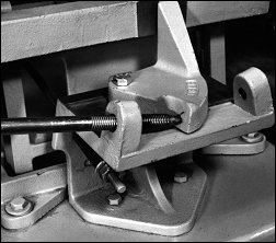
- C. CHECK THE FEED MECHANISM
- To isolate this "system", the saw can be removed from the grinder and the treadle (wheel lift mechanism) should be locked in the "up" position, off the cam (except where noted).
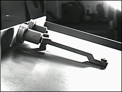
- Check for worn feed finger. The feed finger wears at the point of contact with the tooth face and on the underside.
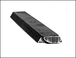
NOTE: Shaping the feed finger to a "teardrop" shape and adjusting the feed finger arm balance spring will minimize (but not eliminate) this wear. Carbide feed fingers are especially susceptible to wear on the underside, behind the carbide point.
- Check the position and travel of the feed finger. The feed finger arm should be located only 1/8" back from the face of the faceplate. The feed finger usually contacts the tooth in the center of the swaged pocket (or just below the Cobalt Chromium Alloy tip).
- Inspect the feed finger cone screws and bushings for wear.
- Inspect the cam and cam followers for wear.
NOTE: Worn cams rarely cause erratic grinding, except if a ridge is built up on one side of the cam. Worn cams may cause other problems, such as improper tooth shape, but at least every tooth is ground the same.
- Make sure the cams are rotating in the right direction. (Refer to motor speed section.)
A QUICK CHECK: Watch the feed finger. When it retracts to pick up the next tooth, it should move about three times as fast as when it is advancing that tooth.
- Time the speed of the feed mechanism
- MAXIMUM: 36 teeth per minute
- RECOMMENDED: 30 teeth per minute
- FOR LARGER SAWS OR A SMOOTHER GRIND: 24 teeth per minute
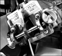
- Confirm that the feed finger is pushing the saw to exactly the same place each time.
A QUICK CHECK: Using a dial indicator on a magnetic base, test for consistency without a saw in place. Next, test as the feed finger is pushing the saw without the grinding head engaged. Lastly, test when the feed finger is pushing the saw and the grinding head is riding the wheel lift cam. In each case the feed finger should repeat to within .002" (.05 mm).
D. CHECK HEAD LIFT MECHANISM
Parts that may need replacing in the head lift are larger and more complex than those in the other systems are. Make sure that the saw support system and feed mechanism are operating correctly before checking the head lift mechanism.
Isolate the head lift by removing the saw from the sharpener and leaving the grinding wheel motor off. For safety, it is a good practice to remove the grinding wheel itself during these tests.
- Check for broken suspender straps. Do the witness marks on the rocker arm and rocker arm carriage still line up?
- Inspect the rocker arm springs. (Refer to Monthly Maintenance No.4)
- Check to see that the wheel adjusting screw pocket is not frozen to the trunnion shaft. The pocket should rotate freely on the trunnion and the head adjusting screw should lift out of the pocket. Oil the pocket and trunnion shaft daily.
- Inspect the wheel adjusting screw nut to be sure it can pivot freely. Clean and lubricate daily.
- Check the head adjusting screw toggle assembly.
- The toggle may back away from the graduated circle carriage if the big spring is too weak or there is binding in the cone screws on the links that support this carriage.
- The head adjusting screw may have bored a hole in the toggle. Correct by grinding the surface of the toggle flat, replacing it or covering it with a carbide plate.
- The threads of the head adjusting screw could be partially stripped, so that the screw is pushed back. Both the screw and the threaded holder may need to be replaced.
- Check for wear or looseness in the cone screws of the rocker head.
NOTE: Most Armstrong band saw sharpeners made before 1980 had one piece cast iron rocker arms. The "feet" or "pads" of these rocker arms wore against the cast iron rocker arm carriage, forming "hollows" after several years, especially in the rocker arm with the "V" foot.
New rocker arm units, with steel "feet" are completely interchangeable with older machines. These new rocker arm assemblies help restore older machines to "like new" operation.
For best results, replace the graduated circle carriage links on the No.4 sharpeners made prior to 1980 at the same time.
E. CHECK GRINDING HEAD ASSEMBLY
To isolate, leave the action motor turned off. Exercise caution when inspecting these components when safety guards have been removed. Replace all safety guards before resuming grinding.
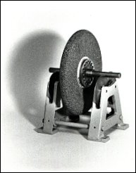
- Remove grinding wheel and balancing collar and check for balance. Use threaded plugs (Part No.510) to balance the wheel.
The balancing collar on a right-hand sharpener should have a left hand thread while the balancing collar on a left-hand sharpener should have a right hand thread. See Also: New Style Arbor Assemblies.
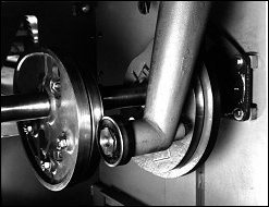
- Inspect the arbor bearings. They should run cool and vibration free. (See Monthly Maintenance No.2.)
- Inspect the V-belt. It should be new and the proper size to fit the pulleys. Replace worn or incorrectly sized belts immediately. Also, check the pulley to see that it is not so badly worn as to allow the V-belt to "bottom-out" in the groove.
- Inspect both the driven and the variable speed pulleys for wear. The spring in the vari-speed pulley should allow for immediate belt take-up when the speed is increased.
- Make sure the grinding wheel arbor is straight and true.
| Previous Page | Table of Contents | Next Page |