|
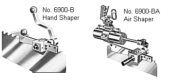
| No. 6900 Armstrong Band Saw Shaper |
Table of Contents
|
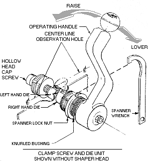
| CENTERING THE SIDE DIES AND LOCATING THE HANDLE |
|
|
| Back To Table Of Contents |
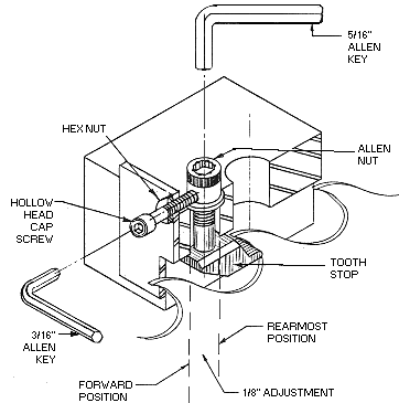
| ADJUSTMENT FOR WIDTH OF POINT |
|
| The side dies are factory ground to your specifications. |
| The dies are ground so that they will produce the desired kerf, or width of finished point, with the tooth stop in the rearmost position. |
| 1/8" adjustment of the tooth stop is provided so that the width of the finished point can be increased as needed up to the following amounts: |
|
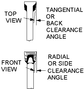
| Standard back clearance angles are 8 degrees tangential or "back" and 3 degree radial or "side" unless otherwise specified. |
| Back To Table Of Contents |
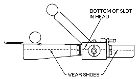
| NO. 6900-B SHAPER ALIGNMENT |
|
| No. 6900 Shapers all require the wear shoes to be in line with the bottom of the slot in the shaper head. A straight edge should be used to ensure proper alignment of both wear shoes to the shaper head. |
| Back To Table Of Contents |
| SHAPING MORE THAN ONE THICKNESS OF SAW |
| Because the clearances are ground into the dies, and the fact that the clearance of the finished point is always in relation to the thickness of the plate, the 1/8" movement of the tooth stop often makes it possible to use the shaper on more than one thickness of saw without changing side dies. |
| Back To Table Of Contents |
| SWAGING FOR PROPER TOOTH POINT |
| The No. 6900 shapers are designed for maximum uniformity, and the saw
itself acts as the stop for the side dies. As a result, it is important to swage to
the proper amount. Generally this will be less than is common with older type
shapers. This has the advantage of producing less work hardening, and less crumbling of the tooth point. In some instances the corner produced on the tooth point may not be as heavy as with the older swaging and shaping procedure. Any reduction in corner, however, is more than out-weighed by the accuracy and precision provided by the No. 6900 shaper and not sufficient to cause a problem. |
| Back To Table Of Contents |
| EFFECTS OF IMPROPER SWAGING |
Swaging the tooth point too wide or too narrow will have the
following effects:
|
| Back To Table Of Contents |
| OPERATING INSTRUCTIONS FOR NO. 6900-BA | ||||||
| ARMSTRONG AIR DRIVEN SHAPER | ||||||
|
||||||
| Back To Table Of Contents | ||||||
| LUBRICATION | ||||||
| All units are lubricated at the factory. The moving parts (side die and clamp screw) will need lubrication with either oil or grease as necessary to reduce wear. | ||||||
| Back To Table Of Contents | ||||||
| SIDE DIE AND TOOTH STOP SELECTOR | ||||||
|
| Back To Table Of Contents |
| SIDE DIE GRINDING NOMENCLATURE |
|
| Back To Table Of Contents |
| INFORMATION FOR ORDERING |
The following specifications are needed to adapt your new shaper to your
exact requirements:
|
| Back To Table Of Contents |
Copyright(c) 1998-02, Armstrong Mfg. Co., All Rights
Reserved |
new products | publications | equipment |