 |
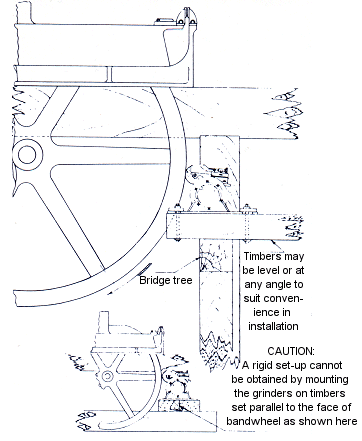
Alignment and setting of grinder:
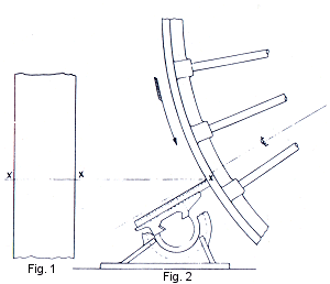
- To align the bed of the grinder with the axis of the band
wheel, scribe a line square across the face of the band wheel as shown at
"X" and "X" in fig. 1.
- With a steel scale or similar tool used as shown in fig. 2,
check at each edge of the band wheel.
- If the bed is not square across face of band wheel,
the face of the band wheel will be ground HOLLOW.
- To obtain the approximate parallel of grinder bed with axis of
band wheel, use the steel scale in the position shown and measure from a selected point on
the upper surface of the carriage out to the face of the band wheel at or near each edge.
- We suggest that for final parallel setting a reasonably wide
surface of the band wheel be ground and then check circumference at each edge of the
ground surface with a steel TAPE.
|
No. 51 Barnhart Operating Instructions
|
 |
Speed of
Band Wheels: The No.
51 Band Wheel Grinder is equipped with ball bearings in arbor, and is suitable for
grinding with band wheels running at full speed. |
Making Grinder Right or Left Hand:
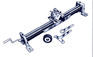
- The long feed screw may be inserted at either end of the bed.
- Use kerosene on dovetail slides and feed screw. Heavy
oil clogs with dust.
|
 |
Depth of Cut and Feed:
- Barnhart Band Wheel Grinders will grind exceptionally fast,
but like all grinding machines there are limits to the abuse they will stand up
under. Remember this is a grinding machine, and accurate work is the objective.
- When grinding cast iron band wheels, do not attempt cuts
deeper than .001" to .002" (.025 to .050 mm). Feed about 4 to 8 turns of
the feed screw per minute.
- Don't set for depth of cut after each cut across the face of
the band wheel. Make a return pass across and note the cut the grinding wheel is
taking. If it is taking a cut of any appreciable depth, the feed in relation to the
depth of cut has been a bit too fast. Accuracy being the principal objective,
refrain from rushing the job. It is good and safe practice to take lighter cuts
with a faster feed than to take deep cuts with a slow feed.
- Keep the cross feed mechanism locked tight with tall nuts when
grinding.
- For finish cut, feed repeatedly across face of band wheel and
keep grinding wheel turning until the grinding wheel virtually quits cutting.
|
| No.
51 Barnhart Operating Instructions |
|
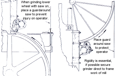 |
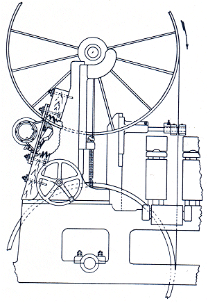
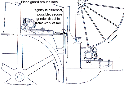
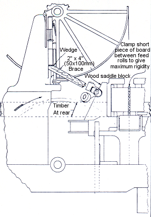
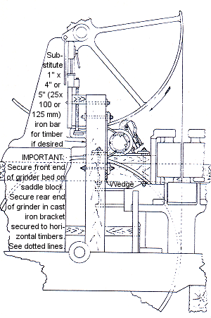
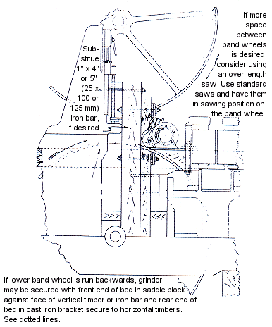
Driving Upper Band Wheel: Use an old band saw with teeth cut off for
driving the upper band wheel for the grinding operation. Cutting off the teeth is an
important safety measure. Where convenient use a standard length saw, and have the
alignment of the band wheels in their sawing position.
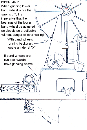
IMPORTANT: Be sure to secure planks around the saw to insure protection to the
operators. Also, cover all the spaces where tools may by accident fall in and go
around the lower band wheel and go between the saw and the band wheel. |
|
 |
 |
| No.
51 Barnhart Operating Instructions |
 |
Taping Wheels With Saw On:
Checking the circumference of the band wheel
when the saw is on can be done without removing the strain on the saw. Before
attempting this procedure, solder the ring on the end of the steel tape. If this is
not done the pressure will break the ring fastening.
Bearings:
This grinder has two SKF No. 6203-2Z ball
bearings in the head. These standard automotive bearings come lubricated from
factory to last entire life of bearing without further lubrication. Replacement
bearings can be obtained from almost any mill supply house or automotive supply house.
Either SKF or other interchangeable makes. |
Grinding Band Wheels Flat
or With Crown Face:
- Band wheels ground with a flat face at full speed of band
wheels will show a slight crown when the band wheels are stopped and measured. This
effect is produced by the action of centrifugal force.
- Should a crown face be desired, the following method of
grinding is suggested:
- First, the wheel should be ground flat, and even thought the
centrifugal force will show a slight crown, the two outside edges of the band wheel should
tape exactly the same. When more crown is desired, the normal crown used is
approximately .001" (.025 mm) for each foot (300 mm) in diameter of the band
wheel. Generally the high point of the crown is back 1/3 from the front edge of the
band wheel on a single-cut saw. The high point is on center on a double-cut
saw.
- To grind the crown, while the wheel is running mark the
location of the high point with a piece of chalk. Make the mark about 1" (25
mm) wide so it can be easily seen. Then grind more material away on each side of
the chalk line to produce the crown without adjusting the set-up for the Barnhart
Grinder. This may be done by moving the Barnhart Grinder head to the outer edge of
the band mill wheel. Then feed in, taking a heavier cut, and traverse towards the
center. Since the grinding wheel is being dressed away during the grinding action,
it develops a crown due to the wear on the grinding wheel. This same operation is
repeated on the opposite edge of the band wheel.
- By placing a straight edge across the face of the wheel, and
using a feeler gauge, or paper, to check the crown at the two edges, you will find that
with a piece of paper on the outside edge of the band wheel that the straight edge will
touch the two pieces of paper and the high point where it was chalked.
|
| No.
51 Barnhart Operating Instructions |
|
 |
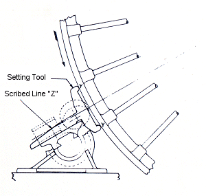
Location of Grinder in Relation to Rim
of and Center of Band Wheel:
- With the stem of the SETTING TOOL resting in the shallow
groove in the upper surface of the CARRIAGE and against one of the shoulders, and the 2
points at "Y" and "Y" contacting the face of the band wheel, the
grinding wheel and the grinding head will be in the correct relative alignment with the
center of the band wheel. And with the scribed line on the side of the stem of the
setting tool at "Z" registering with the scribed line on the upper surface of
the carriage, the bed will be the correct distance from the face of the band wheel.
- Where possible, have this distance from face of band wheel as
shown.
|
Changing Grinding Wheels:
- To remove wheel assembly when replacing worn wheels release
two screws, one on each side of fork, unscrewing these until they come free of the
bearing. Wheel assembly can then be lifted out of fork.
- Before putting on a new grinding wheel, thoroughly remove the
dust from the parts around the grinding wheel. Take all necessary precautions to
prevent dust from getting near the bearings.
- After changing wheels, screw adjustment should be taken up
just enough to remove end play, but so that the wheel spins freely.
Suggestion:
We suggest that you provide a box in which to
keep these instructions, the grinder head and all small parts. Keep box covered. |
Type of Grinding Wheels: Use 6" x 2" x 2" (150 x 50 x 50
mm) resinoid straight face grinding wheels No. 37C24-04B5, or equivalent, made to stand
grinding with band wheels rotating at full speed. It is important to use only the
above type abrasive wheels, which are usually available from abrasive wheel
suppliers. They are recommended for grinding either cast iron or steel band wheels
at any speed.
Note:
In some instances the assemblies shown may
differ from those on your machine. These changes represent improvements made for
more efficient operation. Not all improvements are interchangeable. If the
assembly shown is different from that on your machine, please give description of the
parts you are using. |
|
|
|


